Biến tần | Inverters

Thông tin chi tiết nhất về sản phẩm Frequency inverters MICROMASTER > MICROMASTER 420 của SIEMENS

Biến tần MICROMASTER 420 phù hợp cho nhiều ứng dụng biến tần khác nhau. Nó đặc biệt thích hợp cho các ứng dụng cho máy bơm, quạt và hệ thống băng tải.
Thông tin chi tiết nhất về sản phẩm Frequency inverters MICROMASTER > MICROMASTER 420 của SIEMENS

Overview


MICROMASTER 420, 0.12-3.0 kW, 200-240 V 1 AC, without filter, IP20

Mains operating voltage 200 V to 240 V1 AC 
- Power ranges: 0.12 kW to 3.0 kW
- Without filter
- Degree of protection IP20
 

MICROSMATER 420, 0.12-3.0 kW, 200-240 V 1 AC, with internal filter Cl. A, IP20

Mains operating voltage 200 V to 240 V 1 AC
- Power ranges: 0.12 kW to 3.0 kW
- With internal filter Class A
- Degree of protection IP20
 

MICROMASTER 420, 0.12-5.5 kW, 200-240 V 3 AC, without filter, IP20

Mains operating voltage 200 V to 240 V 3 AC
- Power ranges: 0.12 kW to 5.5 kW
- Without filter
- Degree of protection IP20
 

MICROMASTER 420, 3.0-5.5 kW, 200-240 V 3 AC, with internal filter Cl. A, IP20

Mains operating voltage 200 V to 240 V 3 AC
- Power ranges: 3.0 kW to 5.5 kW
- With internal filter Class A
- Degree of protection IP20
 

MICROMASTER 420, 0.37-11.0 kW, 380-480 V 3 AC, without filter, IP20

Mains operating voltage 380 V to 480 V 3 AC
- Power ranges: 0.37 kW to 11.0 kW
- Without filter
- Degree of protection IP20
 

MICROMASTER 420, 2.2-11.0 kW, 380-480 V 3 AC, with internal filter Cl. A, IP20

Mains operating voltage 380 V to 480 V 3 AC
- Power ranges: 2.2 kW to 11.0 kW
- With internal filter Class A
- Degree of protection IP20


Application

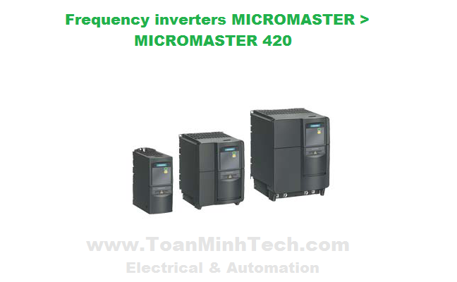
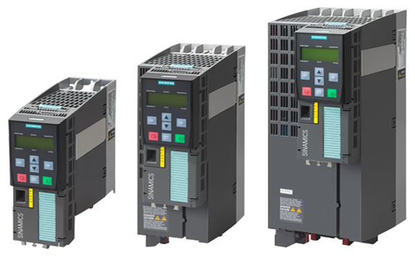
The MICROMASTER 420 inverter is suitable for a variety of variable-speed drive applications.

It is especially suitable for applications for pumps, fans and conveyor systems.
 

It is the ideal cost-optimized frequency inverter solution. The inverter is especially characterized by its customer-oriented performance and ease-of-use. Its large supply-voltage range enables it to be used all over the world.
 

Design

The MICROMASTER 420 has a modular design. The operator panels and communication modules can be easily exchanged without requiring any tools.
 

Main characteristics

- Easy, guided start-up
- Modular construction allows maximum configuration flexibility
- Three fully programmable isolated digital inputs
- One scalable analog input (0 V to 10 V) can also be used as a 4th digital input
- One programmable analog output (0 mA to 20 mA)
- One programmable relay output

30 V DC/5 A, resistive load
250 V AC/2 A, inductive load

- Low-noise motor operation through high pulse frequency, adjustable (observe derating if necessary)
- Complete inverter and motor protection
 

Options (overview)

- EMC filter, Class A/B
- LC filter
- Line commutating chokes
- Output chokes
- Gland plates
- Basic Operator Panel (BOP) for parameterizing the inverter
- Advanced Operator Panel (AOP) with multi-language plain text display
- Asian Advanced Operator Panel (AAOP) with Chinese and English plain text dis­play
- Cyrillic Advanced Operator Panel (CAOP) with Cyrillic, German and English plain text display 
- Communication modules  + PROFIBUS
  + DeviceNet
  + CANopen
- PC connection sets
- Mounting kits for installing the operator panels in the control cabinet doors
- PC start-up programs exe­cutable under Windows 98/NT/2000/XP Professional
- TIA integration with Drive ES
 

International standards

- The MICROMASTER 420 inverter complies with the requirements of the EU low-voltage guideline.
- The MICROMASTER 420 inverter has the CE marking.
- Acc. to uL and cucertified
- c-tick
 

Mechanical features

- Modular design
- Operating temperature: -10 °C to +50 °C (+14 °F to +122 °F)
- Compact housing as a result of high power density
- Easy cable connection, mains and motor connections are separated for optimum electromagnetic compatibility
- Detachable operator panels
- Screwless control terminals
 

Performance features

- Latest IGBT technology
- Digital microprocessor control
- Flux current control (FCC) for improved dynamic response and optimized motor control
- Linear V/f characteristic
- Quadratic V/f characteristic
- Multipoint characteristic (programmable V/f characteristic)
- Flying restart
- Slip compensation
- Automatic restart facility following mains failure or fault
- Internal PI controller for simple process control
- Programmable acceleration/deceleration, 0 s to 650 s
- Ramp smoothing
- Fast current limit (FCL) for trip-free operation
- Fast, repeatable digital input response time
- Fine adjustment using a high resolution 10-bit analog input
- Compound braking for rapid controlled braking
- Four skip frequencies
- Removable "Y" capacitor for use on IT systems (with non-grounded mains supplies, the “Y” capacitor must be removed and an output choke installed)
 

Protection features

- Overload current 1.5 x rated output current (i.e. 150 % overload capability) for 60 s, cycle time 300 s
- Overvoltage/undervoltage protection
- Inverter overtemperature protection
- Motor protection using PTC via digital input (possible with supplementary circuit)
- Earth fault protection
- Short-circuit protection
- I2motor thermal protection
- Locked motor protection
- Stall prevention
- Parameter interlock


Technical specifications

Technical data

MICROMASTER 420

Mains voltage and power ranges


200 V to 240 V 1 AC ±10 %

0.12 kW to 3 kW

200 V to 240 V 3 AC ±10 %

0.12 kW to 5.5 kW

380 V to 480 V 3 AC ±10 %

0.37 kW to 11 kW

Power frequency

47 Hz to 63 Hz

Output frequency

0 ... 650 Hz, (limitation to 550 Hz in production to comply with legal requirements) 1)

Power factor

≥ 0.95

Inverter efficiency

96 % to 97 % (Further information is available on the Internet at:
http://support.automation.siemens.com/WW/view/en/22978972)

Overload capability

Overload current 1.5 x rated output current (i.e. 150 % overload capability) for 60 s, cycle time 300 s

Inrush current

Less than rated input current

Control method

Linear V/f characteristic; quadratic V/f characteristic; multipoint characteristic (programmable V/f characteristic); flux current control (FCC)

Pulse frequency


16 kHz (standard with 230 V 1/3 AC) 
4 kHz (standard with 400 V 3 AC)
2 kHz to 16 kHz (in 2 kHz steps)

Fixed frequencies

7, programmable

Skip frequency ranges

4, programmable

Setpoint resolution


0.01 Hz digital
0.01 Hz serial
10 bit analog

Digital inputs

3 fully programmable isolated digital inputs; switchable PNP/NPN

Analog input

1, for setpoint or PI controller (0 V to 10 V, scaleable or for use as 4th digital input)

Relay outputs

1, programmable, 30 V DC/5 A (resistive load); 250 V AC/2 A (inductive load)

Analog output

1, programmable (0 mA to 20 mA)

Serial interfaces

RS-485, optional RS-232

Motor cable lengths


  • without output choke


max. 50 m (shielded)
max. 100 m (unshielded)

  • with output choke

see variant dependent options

Electromagnetic compatibility


Inverter available with internal EMC filter Class A; available as options are EMC filters to EN 55 011, Class A or Class B

Braking

DC braking, compound braking

Degree of protection

IP20

Operating temperature

–10 °C to +50 °C (+14 °F to +122 °F)

Storage temperature

–40 °C to +70 °C (–40 °F to +158 °F)

Relative humidity

95 % (non-condensing)

Installation altitude

Up to 1000 m above sea level without derating

Standard SCCR
(Short Circuit Current Rating) 2)

100 kA

Protection features for


• Undervoltage

• Overvoltage

• Overload

• Earth faults

• Short circuit

• Stall prevention

• Locked motor protection

• Motor overtemperature

• Inverter overtemperature

• Parameter interlock

Compliance with standards

UL, cUL, CE, c-tick

CE marking

Conformity with low-voltage directive 73/23/EEC

Cooling-air volumetric flow required, dimensions and weights
(without options)


Frame size (FS)

Cooling-air volumetric flow required (l/s)/(CFM)

H x W x D (mm)


Weight, approx. (kg)

A

4.8/10.2

173 x 73 x 149

1.0

B

24/51

202 x 149 x 172

3.3

C

54.9/116.3

245 x 185 x 195

5.0


CFM:
Cubic Feet per Minute


1) For further information see http://support.automation.siemens.com/WW/view/en/107669667

2) Applies to industrial control cabinet installations to NEC article 409/UL 508A.
 

Derating data

Pulse frequency

Output
(for 400 V 3 AC)

Rated output current in A 
for a pulse frequency of

kW

4 kHz

6 kHz

8 kHz

10 kHz

12 kHz

14 kHz

16 kHz

0.37

1.2

1.2

1.2

1.2

1.2

1.2

1.1

0.55

1.6

1.6

1.6

1.6

1.6

1.6

1.1

0.75

2.1

2.1

2.1

2.1

1.6

1.6

1.1

1.1

3.0

3.0

2.7

2.7

1.6

1.6

1.1

1.5

4.0

4.0

2.7

2.7

1.6

1.6

1.1

2.2

5.9

5.9

5.1

5.1

3.6

3.6

2.6

3.0

7.7

7.7

5.1

5.1

3.6

3.6

2.6

4.0

10.2

10.2

6.7

6.7

4.8

4.8

3.6

5.5

13.2

13.2

13.2

13.2

9.6

9.6

7.5

7.5

19.0

18.4

13.2

13.2

9.6

9.6

7.5

11

26.0

26.0

17.9

17.9

13.5

13.5

10.4


Compliance with standards 

CE marking

The MICROMASTER inverters meet the requirements of the Low-Voltage Directive 73/23/EEC.

Low-voltage directive

The inverters comply with the following standards listed in the Official Journal of the European Communities: 

  • EN 60 204

Safety of machinery, electrical equipment of machines

  • EN 61 800-5-1

Electrical power drive systems with variable speed - Part 5-1: Requirements regarding safety - electrical, thermal and energy requirements

Machine directive

The inverters are suitable for installation in machines. Compliance with the machine directive 89/392/EEC requires a separate certificate of conformity. This must be furnished by the plant constructor or the installer of the machine.

EMC directive

  • EN 61 800-3

Variable-speed electric drives 

Part 3: EMC product standard including special test procedure.

The new EMC product standard EN 61 800-3 applies to electrical drive systems as of July 1, 2005. The transition period for the preceding standard EN 61 800-3/A11 dated February 2001 ends on October 1, 2007. The following explanations apply to frequency inverters of the 6SE6 series from Siemens:

- The EMC product standard EN 61 800-3 does not apply directly to a frequency inverter but to a PDS (Power Drive System), which comprises the complete circuitry, motor and cables in addition to the inverter.

- As a rule, frequency inverters are only supplied to qualified technical specialists for installation in machines or plants. A frequency inverter must therefore only be considered as a component which, as such, is not subject to the EMC product standard EN 61 800-3. However, the inverter's instruction manual specifies the conditions under which the product standard can be complied with if the frequency inverter is expanded to become a PDS. For a PDS, the EMC directive in the EU is complied with through observance of the product standard EN 61 800-3 for variable-speed electrical drive systems. The frequency inverters on their own do not generally require marking according to the EMC directive.

- The new EN 61 800-3 of July 2005 no longer distinguishes between "general availability" and "restricted availability". Instead, different categories, namely C1 to C4, are defined according to the environment of the PDS at the place of use:  + Category C1:
Drive systems for rated voltages of < 1000 V for use in the first environment

  + Category C2:
Fixed-location drive systems which are not connected by means of plug-in devices, for rated voltages of < 1000 V. if used in the first environment, installation and start-up may only be carried out by qualified EMC personnel. Warning information must be provided.

Category C3:
Drive systems for rated voltages of < 1000 V, solely for use in the second environment. Warning information must be provided.

Category C4:
Drive systems for rated voltages of ≥ 1000 V or for rated currents of ≥ 400 A or for use in complex systems in the second environment. An EMC plan must be drawn up.

- In the EMC product standard EN 61 800-3, limits for conducted interference voltages and radiated interference are also indicated for the so-called "second environment" (= industrial power supply systems which do not supply households). These limits are lower than the limits of filter class A according to EN 55 011. The use of unfiltered inverters in an industrial environment is permissible provided they are part of a system that is equipped with line filters on the higher-level infeed side.

- With MICROMASTER, power drive systems (PDS) which comply with EMC product standard EN 61 800-3 can be installed (see the installation instructions in the product documentation). The table entitled "Overview of MICROMASTER components and PDS categories" and the MICROMASTER ordering documents show which components the respective PDS installation supports directly.

+ In general, a distinction must be made between the product standards for electrical drive systems (PDS) of the EN 61 800 series of standards (of which Part 3 covers EMC topics) and the product standards for devices/systems/machines etc. This will probably not result in any changes in the practical use of frequency inverters. Since frequency inverters are always part of a PDS and the latter is part of a machine, the manufacturer of the machine must observe various standards depending on the type of machine and the environment, e.g. EN 61 000-3-2 for power supply harmonics and EN 55 011 for radio interference. The PDS product standard alone is therefore inadequate or irrelevant.

- With regard to compliance with limits for power supply harmonics, the EMC product standard EN 61 800-3 for PDS refers to compliance with the EN 61 000-3-2 and EN 61 000-3-12 standards.

- Irrespective of configuration with MICROMASTER and its components, the machine builder can also modify the machines in other ways in order to comply with the EMC directive of the EU. As a rule, the EMC directive of the EU is observed through compliance with the EMC product standards applicable to the machine. If they are not available, the generic standards such as DIN EN 61 000-x-x can be used instead. What is important is that the conducted interference and the radiated interference voltages at the power-supply connection point and outside the machine remain below the corresponding limits. What technical means are used to ensure this is not prescribed.


Overview of MICROMASTER components and PDS categories


First environment
(residential, commercial)


Category C1
Unfiltered devices plus external Class B filter with low leakage currents

Category C2
Devices with an integrated Class B filter 
or devices with an integrated Class A filter plus external supplementary filter Class B
or devices with an integrated Class A filter plus warning information
or unfiltered devices plus external Class A filter plus warning information

Second environment
(industrial)


Category C2
Devices with an integrated Class B filter
or devices with an integrated Class A filter plus external supplementary filter Class B
or devices with an integrated Class A filter
or unfiltered devices plus external Class A filter
Note: 
The requirements of EN 61 800-3 are considerably exceeded if Class B filters are used.

Category C3
Devices with integrated Class A filter
or unfiltered devices plus external Class A filter
Warning information is necessary.
Note:
The requirements of EN 61 800-3 are considerably exceeded if Class A filters are used.

Category C4
Unfiltered devices plus external Class A filter
An EMC plan must be drawn up.
Note:
The requirements of EN 61 800-3 are considerably exceeded if Class A filters are used.


Electromagnetic compatibility

No inadmissible electromagnetic emissions occur if the installation instructions specific to the product are correctly observed.

The table below lists the results of measurements relating to the emissions and immunity to interference of MICROMASTER inverters.

The inverters were installed with shielded motor cables and shielded control cables in accordance with the directives.


EMC phenomenon
Standard/test

Relevant criteria

Limit value

Emitted interference
EN 61 800-3

Conducted via mains cable

150 kHz to 30 MHz

Unfiltered devices, not tested.
All devices with an internal/external filter:
Depending on the type of filter and on the envisaged PDS installation:
Category C1:
Limit value complies with EN 55 011, Class B
Category C2:
Limit value complies with EN 55 011, Class A, Group 1.
In addition, all devices with an internal/external filter comply with the limit value for category C3 installations.
Limit value complies with EN 55 011, Class A, Group 2.

Emitted by the drive

30 MHz to 1 GHz

All devices.
Limit value complies with EN 55 011, Class A, Group 1.

ESD immunity
EN 61 000-4-2

ESD through air discharge

Test severity level 3

8 kV

ESD through contact discharge

Test severity level 3

6 kV

Immunity to electrical fields 
EN 61 000-4-3

Electrical field applied to unit

Test severity level 3

80 MHz to 1 GHz

10 V/m

Immunity to burst interference 
EN 61 000-4-4

Applied to all cable terminations

Test severity level 4

4 kV

Surge immunity
EN 61 000-4-5

Applied to mains cables

Test severity level 3

2 kV

Immunity to RFI emissions, conducted
EN 61 000-4-6

Applied to mains, motor and control cables

Test severity level 3
0.15 MHz to 80 MHz
80 % AM (1 kHz)

10 V


UL listing

UL and cUL listed power conversion equipment of UL category NMMS, in accordance with UL508C.

UL list number E121068 and E192450

For use in environments with pollution degree 2.

Also refer to the Internet at http://www.ul.com/


Dimensional drawings

Dimensional drawings
 

Circuit diagrams

Schematics
 

Assets

Technical specifications
 
(Nguyễn Thảo Trường - http://DienElectric.Com theo Siemens)
Gọi điện thoại